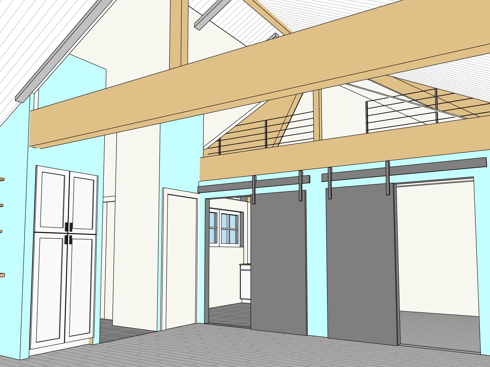
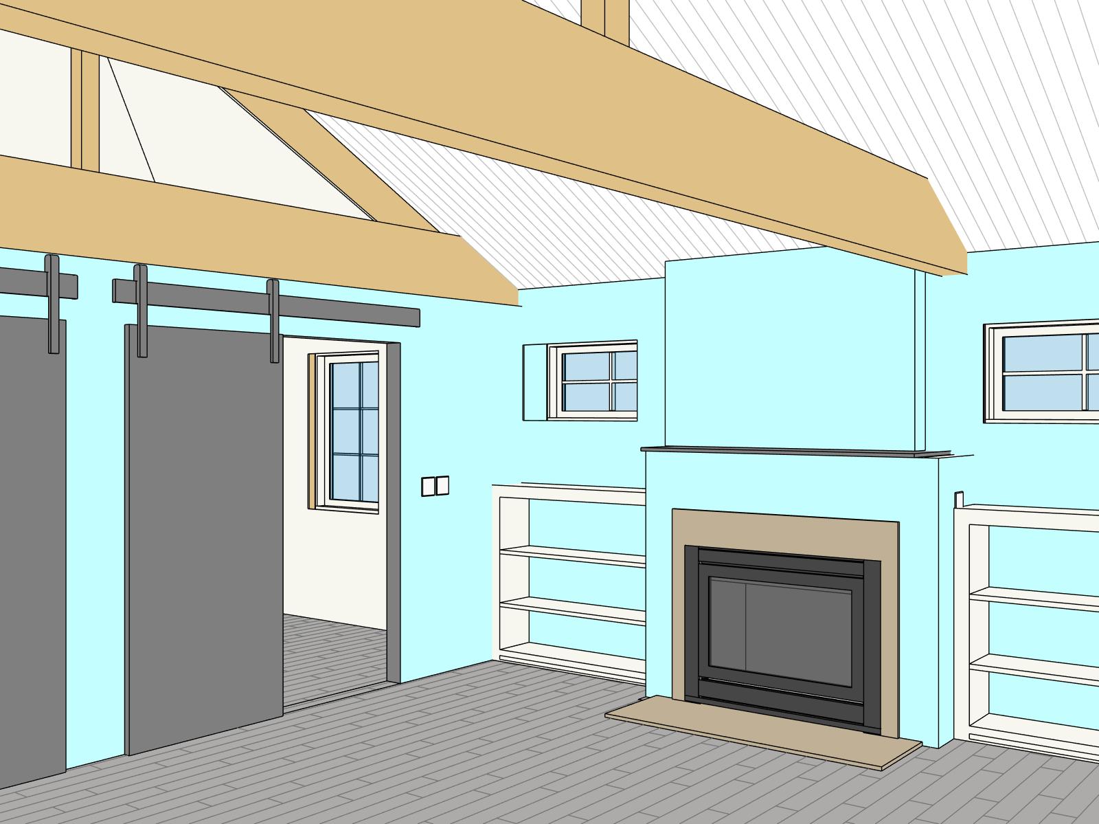
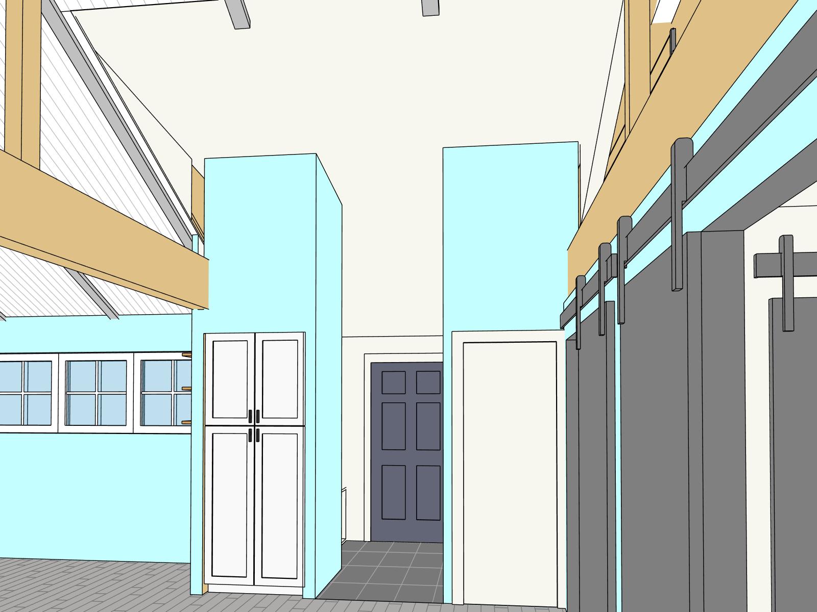
Throughout your home renovation project your architect should be able to provide you with 3D floor plans and other 3D images of the design. These are incredibly helpful for all involved, especially at the preliminary design stage. However, to receive permits and to have your project built, you will need a comprehensive set of construction documents. There is a lot of information that needs to be conveyed and the bulk of this information gets conveyed in plans, sections and elevations. These are 2d drawings that are packed with information, and many people have difficulty understanding how to read these drawings.
A previous post covered how to read floor plans.
This post will cover how to read your section drawings.
Sections depict the vertical relationships between the spaces shown on your floor plans. They relate spaces above and below each other and provide information about wall heights, floor-to-floor heights, stair clearances and roof slopes, among other things. While your plans show the horizontal relationships between walls in a room, sections show you how tall those walls are. Together, these two drawing types provide an accurate description of the size and shape of the space you are trying to create.
Let’s look a little more in depth at some of the information shown in your sections.
Sections show your ceiling heights. Heights from 8 to 10 feet are common. People often request heights greater than that, not fully realizing how high a 10 foot ceiling really is. A graphical silhouette can help, give your drawing scale, though these are usually not shown on construction drawings. Above 10 ft you may be required to have thicker walls which can add expense to your project and cut into your finished floor space.
Sections also show your floor assembly depth. This is generally the sum of the floor joist and the subfloor above the joist, to which your finished floor will attach. Joists in the 12” range are common, but if you want a really wide open plan you may end up needing deeper joists, which would increase the depth of your floor assembly. This is usually not visible space, but increasing this depth can affect stairs, overall building height and cost.
Sections also show detail callout markers. These are usually rectangular dashed line shapes with a bubble and a number. This alerts you to the fact that there is more information about a specific area in your project on another drawing. This is because every project will have some special conditions that require the architect to provide more detailed drawings. This detail can’t be seen at the typical scale of the section, so a blow up drawing of one small area is provided. If the mark next to the callout says 3/A501 the additional detail can be found at drawing #3 on sheet number A500.


